NURBSlib_EVM
python scripts and macros to make NURBS surfaces in FreeCAD -
ALL DEVELOPMENT HAS MIGRATED TO SILK
NURBSlib_EVM
My python scripts for creating surfaces in FreeCAD.
This is the rough workflow prototyping phase. most basic objects are now parametric. The workflow is based on sketches drawn in FreeCAD 0.17 or later. The sketches are used to control NURBS curves and surfaces.
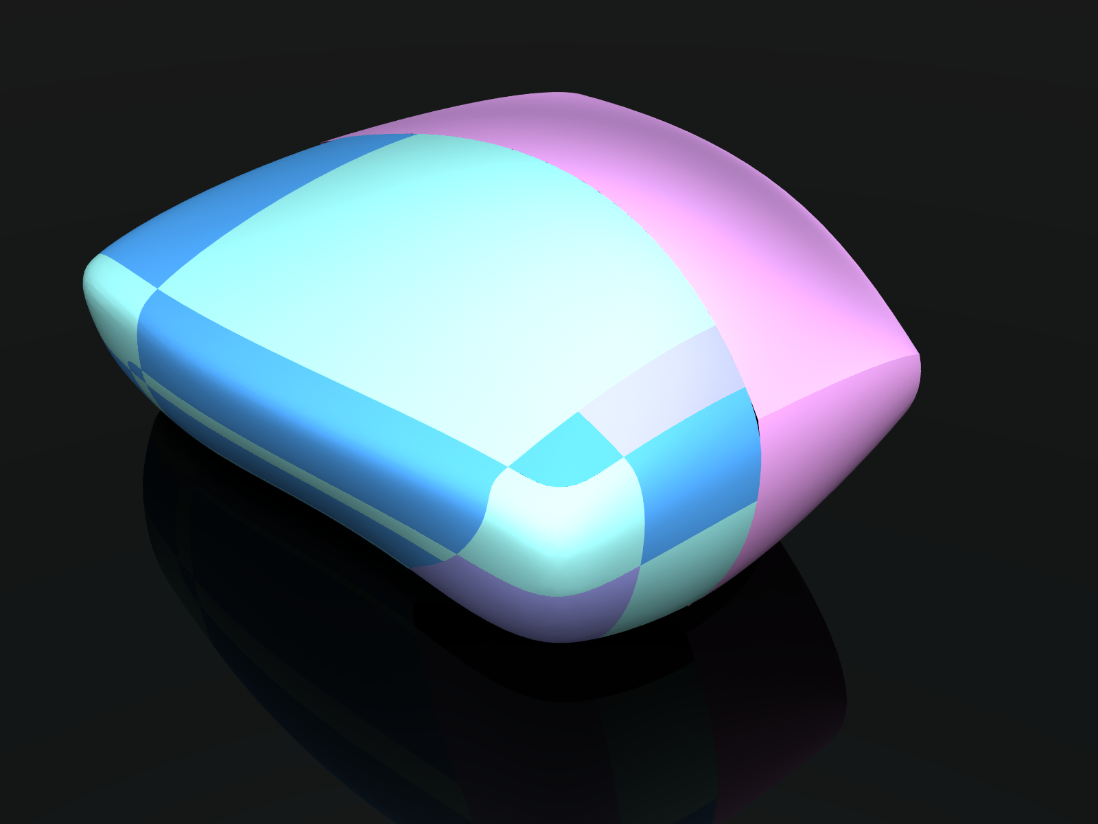
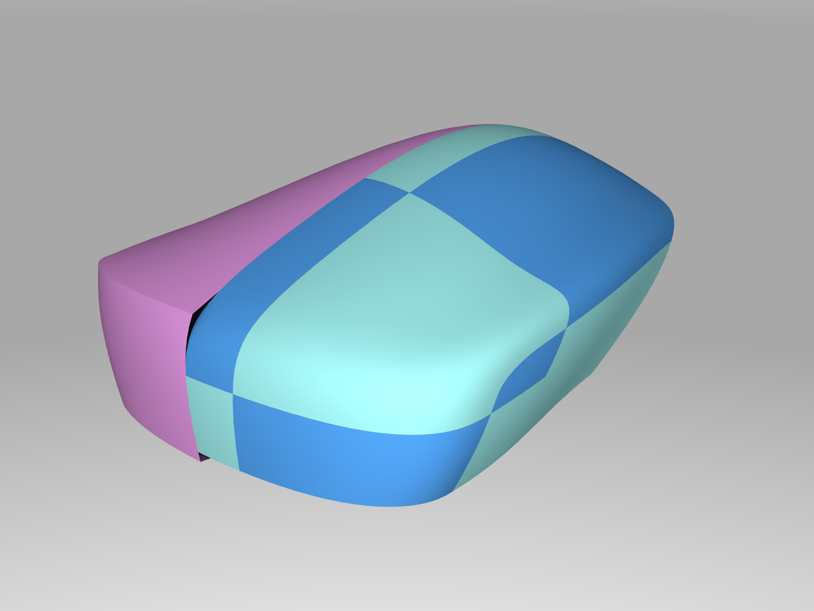
What does it do right now? Here is my favorite model so far. It shows control of an overall shape with ‘main’ sketches, and automatic ‘blending’ of the corners of the main surfaces to obtain curvature continuity (G2).
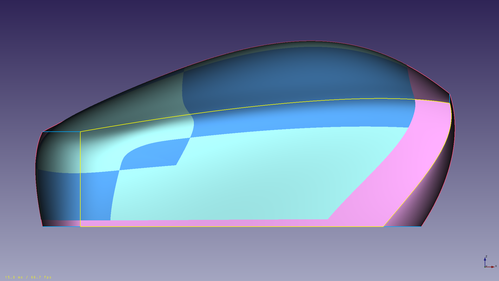
The next image shows the current required steps:
-create and position sketches using FreeCAD (white lines)
-convert the sketches to polygons (blues lines)
-convert the polygons to curves (black lines), or combine the polygons into grids (light blues lines)
-convert the grids to surfaces
-trim/clip sections of curves / surfaces (several steps needed here)
-blend the sections
There is a fair amount of work to setup a blended model, but the payoff is that all the work is parametric, so one can go back and edit the initial overall sketch, and everything, including the blends will update. This is shown below. Moving the white lines of the sketch sculpts the blended surface.
The ultimate goal is to implement a set of tools that require very few points and tangents/normals to generate NURBS surfaces of high continuity. I have some ideas as to what constitutes an efficient and intuitive input/interface structure. This is very personal, and cannot address all individual preferences.
Ideally, the user interaction with the points/normals would be analogous to manipulating a coarse mesh, like subdivision surfaces. The main difference with subdivision surfaces being that with full NURBS, we can have perfect conics, no intrinsic continuity limits, and the ‘handles’ stay on the surface itself. So when we dimension/constrain the handles, we are dimensioning the surface itself.
What this means in practice is that eventually the user will not need to know anything about control points, knot vectors, or weights. At this stage however, a minimum understanding of control points is still necessary to use the tools.
These are not the ‘classic’ surfacing tools like sweep, loft, blend, trim, etc, although there are many parallels.
FreeCAD already has some of these tools in the Part module and i believe the PartDesign module is slated to get improved versions soon. OpenCascade itself already has all of these functions built in, but c++ is beyond my skills right now, so i’ll stick yo python.
All scripts (file extension .py and .fcmacro) in this repository are offered under the terms of the GPLv3
All models (file extension .fcstd). and icon files (file extension .svg) in this repository are offered under the terms of CC-BY
I have started making some tutorials:
go to tutorial 0.01, ControlPoly4 and CubicCurve4
go to Tutorial 0.02, ControlGrid44 and CubicSurface44
go to Tutorial 0.03 Point_onCurve ControlPoly4_segment ControlPoly6 and CubicCurve6
Workbench release planned soon.
NURBS in general, and what these scripts are trying to do
For now, my focus is on skinning sets of 3 or 4 curves in a loop, and then smoothing out the seams between neighboring surfaces.
The skinning routines should be
-repeatable: produce the same result for the same inputs
-consistent: produce a scaled result for a scaled input.
The seams joining adjacent surfaces should always have the same level of continuity as the adjacent curves at the surface corners.
I am learning as i go, so i am trying to ‘juice’ the most out of the basic NURBS formulations before moving on to more complex forms. High degrees and complex knot vectors give great smoothness, but few of the control points correspond to actual surface points, so they are challenging to fit among other engineering forms and constrain correctly.
The cubic bezier form is the simplest form that can connect two points with specified tangents (G1), and i am exploring its limits. The weight control interface is incomplete, but curve weights are incorporated into the surfaces in a crude way. Arcs can be converted to rational Bezier and used in surfaces. I have a basic quadrilateral surface patch, and a rudimentary triangular suface patch (one collapsed edge/corner). It is theoretically possible to modify the inner control points and weights of a bezier to control the curvature (G2) across the seams in some cases, but this requires manipulating several control points at once, and maintaining tangent continuity is hard to begin with.
For now, the Bezier curves and surfaces are considered to be ‘rough drafts’ of the final surfaces. Easy to specify, cheap to tesselate. Sometimes they may even be adequate to patch a hole in a shell, if the surrounding surfaces are simple.
In order to have isolated curvature at each curve endpoint, i made a 6 control point cubic curve and associated 6X6 surface. This surface type does not have a triangle version yet. Included are utilites to convert cubic Bezier and arcs to this curve type.
This will open up the possibility of using the 3rd and 4th points to control start and end curvature respectively. This can be done without interfering with the use of the 2nd and 5th control points to set tangents. Right now the curvature matching must be done by hand, but for any particular value of curvature desired at a curve connection, there are many possible control points positions. These additional degrees of freedom will (i hope) allow the possibility of controlling the derivative of curvature (highlight flow).